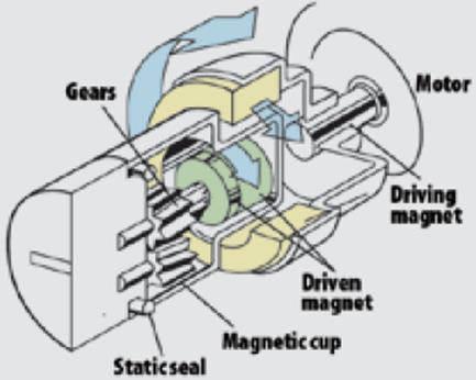
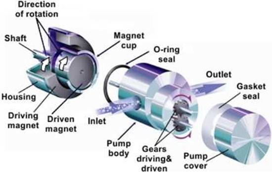
Magnetic external gear pump
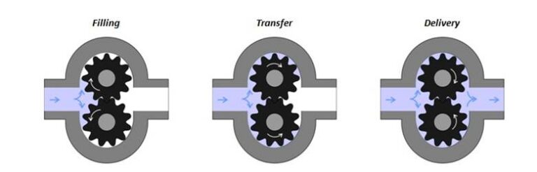
This is a magnetic gear pump designed with identical gears. The two gears rotate in opposite directions. The driving gear is powered by the electric motor through the magnetic coupling so that it can drive the idler gear. Each gear is mounted on a shaft that is supported by bearings. When the gears on the inlet side come out of the mesh, the liquid volume increases on the suction side. When the gears start spinning against the pump casing, the liquid moves into the cavity and gets trapped by the gear teeth. The trapped fluid moves around the casing from the inlet to the outlet. When the gear teeth mesh on the outlet side of the pump, the volume of liquid reduces and the liquid is drained under pressure.
Magnetic gear pump manufacturers design the pump such that the liquid cannot return from the center between the gears if the gears are in mesh. Because of the tight tolerance between the pump gears and the housing, the pump produces suction on the inlet side and prevents fluid from returning from the outlet side. For this type of magnetic gear pump, spur gears, helical gears, or herringbone gears can be used.
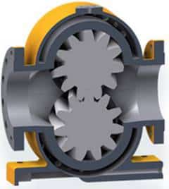
Figure: Magnetic external gear pump.
Magnetic internal gear pump
This pump works similarly to the external type of gear pump but it has a dissimilar size of the two gears. One of the meshing gears rotates in the other gear. The internal gear is the larger one and its teeth protrude inwards. The smallest external gear within this area is located eccentrically. Magnetic gear pump manufacturers design this pump such that the gears mesh at specific points. The idler gear is held in place by use of a pinion and bushing mounted in the pump. This pump is non-pulsating and it can run dry for a short time. It is also bi-directional making it suitable for loading and unloading vessels. This magnetic gear pump is reliable and easy to maintain and use.
The volume of liquid increases when the gears on the inlet side are disengaged. As the gears rotate relative to the housing, the liquid moves into the pump cavity and it is trapped by gear teeth. The trapped liquid then moves around the housing from the suction to the discharge side. When the outlet side gears mesh, the liquid volume reduces, and the liquid is drained.
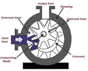
Figure: Magnetic internal gear pump.
Sanitary magnetic gear pump
This pump designed to enhance high levels of hygiene. Magnetic gear pump manufacturers design this pump for use in applications that need high levels of hygiene such as foods and beverage processing and pharmaceuticals. The hygiene levels in this pump are achieved by considering several factors such as the material used to make the pump and design considerations. The material used must be inert to the product being transported and also be safe for human consumption. The design should make the pump easy to clean to ensure there are no odors or accumulation of dirt inside the pump.