Single Stage Centrifugal Pump
What is a Single Stage Centrifugal Pump?
A single-stage centrifugal pump is made up of one diffuser and an impeller mounted on a shaft and enclosed in a pump casing. Like any other pump, a single-stage centrifugal pump is designed to move water from one place to another by converting the mechanical energy of the impeller into the pressure energy of the fluid. However, as its name suggests it pressurizes the fluid in one stage involving a single impeller and a diffuser. It is one of the seven types of centrifugal pumps-the most common types of pumps accounting for about 70 % of all types of pumps used for industrial and domestic uses. It is also one of the classifications of centrifugal pumps by the number of impellers, the other two are dual-stage and multistage centrifugal pumps. A single-stage centrifugal pump is one of the simplest designs of pumps available in the market. The impeller design of this pump can be varied by incorporating mechanical seals for the pump to handle different application requirements e.g., pumping clean, dirty, and solids laden liquids. Single-stage centrifugal pumps are preferred for applications with huge flow rates and low-pressure fixing. Thus, they are mostly used for pumping services with a high-flow & low to moderate total dynamic head (TDH).

Figure: single-stage centrifugal pump (picture: mechanicalboost.com)
Working principle of single-stage centrifugal pumps
The single-stage centrifugal pumps operate as follows: Before starting, the pump casing is first filled with the liquid to be transferred- a process known as pump priming. Once the pump is started, the motor drives the shaft and the impeller at a very high speed, the liquid in the pump casing rotates with the impeller, and more liquid is drawn into the pump. Due to the centrifugal force acting on the impeller, the fluid is thrown from the center of the impeller to the outer edges and it finally enters the volute casing at a very high speed and kinetic energy. In the volute casing, the speed of the fluid slowly decreases due to the gradual expansion of the flow path, and some of the kinetic energy is converted into static pressure energy. After leaving the volute casing, the fluid enters the discharge pipe at a very high pressure which allows it to be moved to the place where it is required.
The displacement of the liquid from the center of the impeller to the outer edges creates a vacuum at the center of the impeller. It is this vacuum that causes more and more liquid to be sucked into the pump when the pump is running. As long as the impeller rotates the liquid will be continuously sucked in and discharged.
Components of a single-stage centrifugal pump
The main parts of a single-stage centrifugal pump are the impeller, pump casing, and shaft.
Single stage pump impeller
The impeller is the part of the pump comprising of vanes and blades. The main function of the impeller is to directly transfer the mechanical energy from the prime mover (mostly electric motor) to the fluid to increase fluid pressure and flow rate. The design of the impeller is one of the most important determinants of pump performance. A proper impeller design should be such that it optimizes flow, eliminates turbulence, and maximizes efficiency. Pump impellers are fabricated from metallic materials such as steel, iron, or bronze, as well as plastics. The impeller usually consists of 6 to 12 blades.
There are three main types of impellers: open type, semi-open type, and closed type. An open impeller consists of vanes that are free on both sides. This type of impeller is simple to manufacture and clean, but it is structurally weak and has low efficiency. It is mostly used in small diameter pumps and pumps dealing with suspended solids. A semi-closed impeller consists of vanes that rea closed on the delivery side and open on the suction side. These types of impellers are used medium-diameter pumps and are suitable for the transfer of liquids consisting of particles e.g., sewage. A closed impeller is covered on either side with front and rear cover plates. The single-stage centrifugal pump utilizes this type of impeller. The closed impeller is highly efficient for conveying cleaning liquid without impurities.
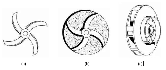
Figure: Types of impellers: (a) open impeller (b) semi-closed impeller (c) closed impeller
Pump casing
The function of the pump casing is to house the impeller such that the liquid can be drawn in and discharged due to the rotation effect of the impeller. The single-stage centrifugal pump uses a volute type of casing. For this casing, the cross-sectional area of the liquid passage gradually enlarges as it approaches the discharge nozzle. This causes the speed of the liquid to gradually decrease as some of the kinetic energy converts into fluid pressure.
Pump shaft
The function of the pump shaft is to transfer torque and mechanical power from the motor to the impeller via coupling to the motor shaft. The shaft usually comes with shaft seals for the following reasons:
- To prevent the liquid in the pump casing from leaking out along the shaft
- To prevent the outside air from leaking into the pump casing
Shaft sealing devices consist of packing, packing rings, and mechanical seals. Generally, mechanical seals work by creating a relative motion between the moving ring fixed on the shaft and the stationary ring mounted on the pump casing. The filler comprises oil or graphite fixed asbestos rope.
Priming the single-stage centrifugal pump
Priming is an important step during the initial startup process of a single-stage centrifugal pump because the pump is not capable of pumping air. The pump-priming process involves adding water or the liquid to be pumped into the pump casing to drive out and to ensure that the impeller is submerged in the fluid. Priming can be done manually, using a vacuum pump, using a jet pump, or with a separator.
Applications of single-stage centrifugal pump
- In agriculture, domestic and residential water supply systems, and water mains.
- chemical and petrochemical industry for transferring liquid at required flow rate and pressure for chemical reactions to take place
- Power plants e.g., in thermal power plants as boiler feed pumps or condensate pumps and nuclear power plants as the secondary or primary system.
- fire-fighting systems
- mining and metallurgy industries to drain and cool water supplies
- water treatment plants
- air-conditioning systems
- cooling systems
- pulp and paper industry
Advantages of single-stage centrifugal pump
- Very simple and compact construction
- small volume hence little space requirement
- very stable in performance
- lightweight compared to other types of pumps such as multi-stage pump
- Easy to operate and repair
- Available in a variety of designs: horizontal, vertical, single-suction, and double-suction configurations
- It is easy to maintain
- high reliability
- It can operate at high speed
- It can handle a large flow volume
- it may cost a little less compared to dual-stage and multi-stage counterparts
Disadvantages of single-stage centrifugal pump
- The pump has low-performance efficiency
- It can only pump fluid for a short distance since it only has a single stage for fluid pressurization
- Low-pressure head.
- Requires priming for initial startup
- may have high noise levels
Basic maintenance of a single-stage centrifugal pump
Maintenance of mechanical components
- The mechanical mounting point should be kept secure
- pump flanges and coupling must always remain tight
- mechanical seal and packing should be checked regularly and replaced if worn out to prevent leakage
- All worn out parts should be replaced
- The impeller and [pipe work must be regularly unclogged
- The bearing should be sufferingly lubricated
Maintenance of electrical components:
- The wiring system should be kept free of loose connections
- The stator should be inspected for arching and overheating
- The motor windings should be free of dirt and dust
- Inspect for any insulation failure
Troubleshooting single-stage centrifugal pump
The pump does not start
- No electricity supplies
- Loose connections (check pump wiring and tighten any loose connections)
- The fuse has blown out (replace the fuse)
- Defective motor winding
- Available voltage is less (ensure the right voltage supply)
Zero flow after start-up or the pump gives little discharge
- Air in pump or suction pipework (ensure pump and piping system is filled with water)
- The suction lift is too high (ensure there is no obstruction at the pump inlet)
- Impeller strainer or check valve is clogged
- Wrong direction of rotation (reverse polarities)
- Excessive wear on the impeller due to prolonged operation or high sand content in pumped water
- Leakage in the pipe (replace damaged pipes)
- The riser pipe is partly chocked by impurities (unclog the pipes)
- The impeller is lodged with impurities
- The discharge pipe is coated with depositions
- The discharge valve is partly closed (ensure discharge valve is fully open)
The total head developed is too low
- leaking check valve or foot valve (replace the valves)
- Excessively worn-out pump components e.g., the impeller (replace worn-out parts)
- The discharge pipe is coated with impurities (clean the impurities)
- The discharge line is closed and priming air can’t find the way out (open the discharge line)
- leakage in the mechanical seals, packing ring (replace mechanical seals, packing ring)
Bearing overheating
- Poor coupling alignment (realign pump and coupling, check coupling rubber)
- Bearing covers are too tight (check and loosen cover appropriately)
- Excess grease (drain excess grease)
- Grease is contaminated or dirty (clean the bearings and housing)
High noise level and pump vibration
- Worn out impeller
- Oblique (inspect shaft and replace if necessary)
- Unbalanced parts (rebalance pump parts)
- Poor coupling alignment (realign pump and coupling)
- Air in liquid (ensure the suction pipe is submerged in the liquid so that vortexes are not created on the surface of the liquid, increase depth of suction pipe)
- Pump working outside duty range (check duty point)
- Pump working in cavitation (Too low Net Positive suction head, inspect suction losses, fully open the inlet valve, increase suction)
Summary
This article discusses the single-stage centrifugal pump, its operation, and its main components. It also highlights some of the applications of the pump, its advantages, and its disadvantages. A single-stage centrifugal pump has been described as a pump comprising of a single impeller. The pump pressurizes the fluid through a single stage. A single-stage centrifugal pump is made up of a similar main component to any other pump type including impeller, pump casing, shaft, shaft seals, suction, and discharge pipes. The pump finds application in diverse engineering fields such as agriculture, power production, chemical manufacturing, mining and metallurgy, pulp and paper industry. Where huge flow rates and low-pressure fixing is required, a single-stage centrifugal pump is best suited for the role. Many people opt for this pump in their uses because it is cost-effective, easy to maintain, compact in size, very stable in performance, highly reliable, and can handle a large volume of flow. However, the pump may not be suitable for some applications because it is associated with certain limitations such as low-pressure head, low-performance efficiency, and sometimes high noise levels. The pump performance and lifetime can be enhanced through regular maintenance of mechanical and electrical components. Mechanical maintenance may entail the replacement of worn-out parts, mechanical seals, shaft alignment, and tightening of flanges and coupling. Electrical maintenance mainly pertains to the electrical wiring circuit of the motor which should be kept free of loose connections or dirt. This article also provides a quick guide on how to troubleshoot a single-stage centrifugal pump to fix some common faults in the pump system.